How Arduino Sensors Actually Work
If you’re going to use your Arduino UNO to its fullest potential, then you’ll need to pair it with one or more extra components. After all, an Arduino that’s incapable of interacting with the world around it isn’t much fun!
Components in an electronic circuit can be divided into three categories:
+ Input devices, like buttons, switches, and sensors.
+ Processors, such as standalone microcontrollers and single board computers like the Arduino, ESP and Raspberry Pi.
+ Outputs (or actuators), which convert voltages into sound waves or lights that we can sense.

In this post, we’ll focus on the first part of this chain. All input devices can be classed as sensors. These are components whose output (usually an analog voltage) changes according to a given property of the surrounding environment. This change might be anything from a change in the temperature, to gravity, to electromagnetic charge. Sensors are incredibly useful devices. Without them, electrical circuitry just wouldn’t make much sense!
You’ll find it easy to incorporate a sensors into your projects using an Arduino, particularly if they're built into a breakout board. But with so many types of sensor to choose from, deciding which to use may not be so simple. In this blog post, we tried to cover the most popular Arduino sensors – but bear in mind that these sensors can also be used with other microcontrollers.
Arduino sensors come in all sorts of shapes and sizes. Here, we’ll examine five different types in detail and try to determine how (and why) we might implement each into our circuit designs. We’ll also talk about where they can be used, what their advantages and drawbacks are, and hopefully, provide you with a little bit of inspiration for your project. Let's begin!
Temperature sensors
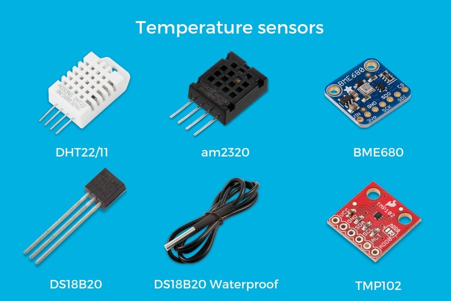
A temperature sensor, as you can probably guess, detects changes in ambient temperature. They’re a key component in any device that relies on this information, like an automated gardening system which opens or closes a window in a greenhouse depending on the temperature inside. You'll often find temperature and humidity sensors bundled within the same breakout board.
Thermostat
Among the most common sorts of temperature sensor is the thermostat. Most thermostats contain two metallic strips, placed one on top of the other. One changes shape in response to changes in temperature, causing both to bend and touch a nearby contact. Thermostats are inexpensive to produce, but they aren’t as accurate as other sorts of temperature-sensitive sensors, like thermistors.
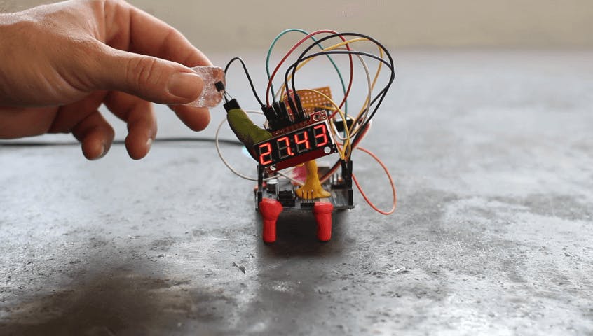
The numeric readout provided by our DIY digital thermometer is a simple application of the temperature sensor. If you can keep it moisture-tight, you’ll be able to leave it in your refrigerator, and see at a glance how cold it is inside. This device is a variety of digital temperature sensor, which outputs values along a single wire; it doesn’t even need to receive power along a separate one, making it a convenient choice.
Thermistors
All conductive material become less conductive when exposed to heat. A thermistor exploits this phenomenon in a controlled way, and allows a circuit to figure out the ambient temperature by recording the resistance. Thermistors come in two sorts: negative temperature coefficient (NTC) and positive temperature coefficient (PTC). The former offers less resistance as the temperature rises; the latter offers more. By choosing the right one, you’ll be able to keep your circuit simple.
Our NodeMCU-powered smart-thermostat incorporates the DHT22, which uses a thermistor to measure temperature, and another embedded sensor to measure humidity. The two sensors are connected internally to a microcontroller which outputs a digital signal along a single wire. This extra stuff slows the circuit down a little, with samples being taken every two seconds – but for our purposes this wasn’t a problem.
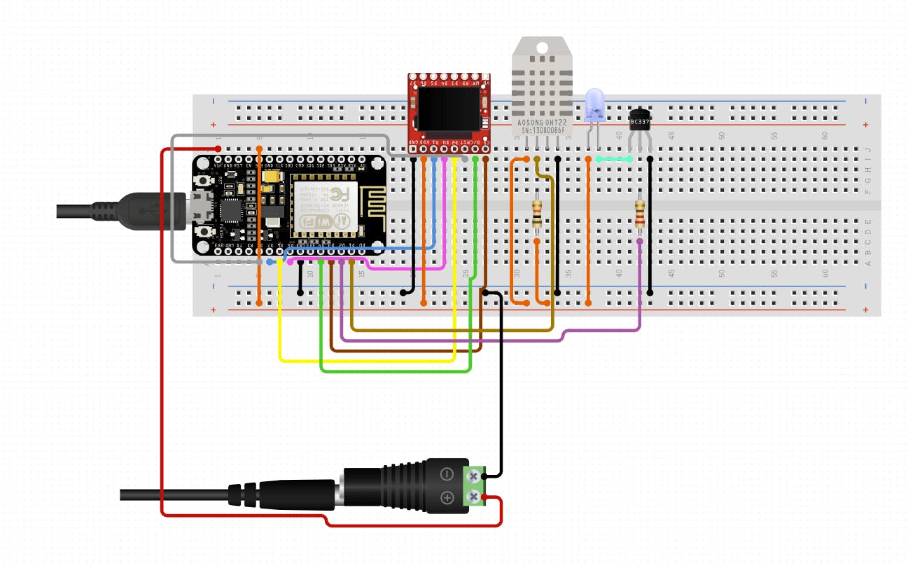
The DHT22 also features prominently in our Arduino-based weather station project, which can be used to submit your local temperature to a wider network of public and private weather stations, helping everyone in the process.

Thermocouples
A thermocouple is made from a couple (get it?) of junctions of different metals, joined together. The resistance of one will alter differently to the other, so as the heat rises, the difference in voltage between the ends of the two will change.
A thermocouple is capable of measuring far greater ranges in temperature than a thermistor, which makes them suitable for high-stress environments, like the interior of a gas turbine or an engine. This advantage, however, comes at the cost of accuracy: thermocouples are nowhere near as accurate as thermistors.
RTD
A Resistance Temperature Detector, or RTD, works pretty much like a thermistor, except that it’s made from a coil of highly conductive metal, whose conductivity changes in response to the local temperature. They represent a compromise between the thermocouple and the thermistor, in that they can measure more accurately than the thermocouple, over a greater range than the thermistor. Where the RTD falls down is response time; while the other components we’ve mentioned will react to temperature changes within a few seconds, the RTD can sometimes take up to a minute. As such, it’s better at observing longer trends than reacting to short-term thermal shocks.
Applications for temperature sensors
So where are these technologies applied? A common example of a temperature sensor is one related to home automation – a thermostat. This device uses a temperature sensor(or several), to track the temperature in a house, and uses the information collected to turn the heating up or down. Without it, the boiler wouldn’t know whether to boil more water, and it would be impossible to maintain a consistent temperature.
The same principles apply to your oven – built-in temperature sensors inside the compartment constantly check to see whether the temperature is above or below the desired level. If things are too warm or too cold, it’ll adjust the power going to the heating elements. Similar arrangements exist in other appliances where temperature needs to be controlled – including fridges, air-conditioning units, the nozzle on your 3D printer, the tip of your soldering iron and the CPU on your computer.
How to Choose a Temperature Sensor
Accuracy
Of the components we’ve mentioned, a thermistor is by far the most accurate.
Range
In a thermocouple, the actual sensor is shielded, leaving only the metal arms to which it’s attached exposed to higher temperatures. As such, it’s a great choice for high-temperature situations.
Interface (analog/digital)
Pretty much all temperature sensors put out an analog current; you’ll need to use an ADC to turn their outputs into a useable digital value.
Response Time
If you’re measuring very rapid changes in temperature, then you need an accordingly fast response time. In this respect, thermistors and thermocouples come out on top; they’re able to respond within just a few hundred milliseconds, while an RTD might take ten times longer or more.
Distance sensors
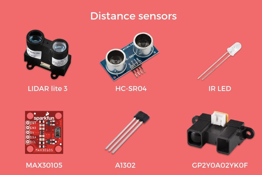
As with temperature, there are several electronic means of measuring distance. For the most part, they work in a similar way: by putting out an impulse and examining the return signal for changes, much like echolocation.
These sensors use the Time of Flight (ToF) principle, and calculate distance using the following equation:

LIDAR
LIDAR (or light-detection and ranging) uses a laser to send a stream of pulses toward a distant target. The delay between the impulse and the reflection arriving back at the sensor,along with the speed of light (which is 299,792,458 metres per second) can be used to work out the distance using the equation above. By doing this thousands of times a second in multiple directions, it's possible to generate a three-dimensional image of the area. In this way, very detailed and accurate maps can be created without the need for an on-site survey team. Lidar can generate images of crime scenes for later study by forensic scientists, detect the speed of passing vehicles, and even generate terrain data for use in video games.
Ultrasonic sensors
Ultrasonic sensors do the same thing using high-frequency sounds rather than light. They pair an ultrasonic emitter with a miniature microphone designed to detect the reflections. They don’t draw much current, but the information they provide is of a low resolution and refresh rate. And, naturally, they’re able to operate in the dark. In this case, distance is calculated using the ToF equation with the speed of sound travelling through air. Given that this varies according to things like humidity, pressure and temperature, ultrasonic sensors aren't quite as accurate as LIDAR - particularly over long distances.
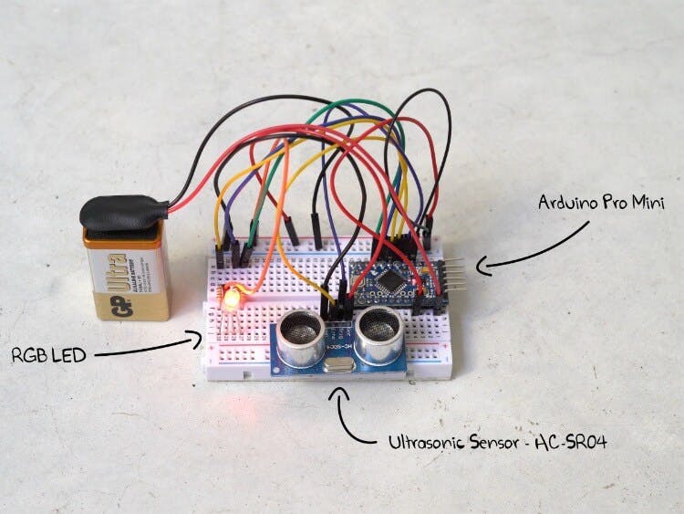
We’ve used the HC-SR04 ultrasonic sensor in our Arduino-based air-gate project. It’ll detect whenever a drone passes close by, and change color accordingly. Perfect for practicing your piloting skills!
IR LED sensors
Infrared LED sensors work using light-emitting diodes. Their maximum range is pretty limited. As such, they’re ideal for measuring very short distances. A great example would be in 3d printing, where an LED sensor is used to measure (and compensate for) minute changes in the distance between the print-surface and the print-head.
Hall effect proximity sensors
Hall effect sensors put out a voltage depending on the surrounding magnetic field, thereby exploiting a principle discovered by Edwin Hall in the late 19th century. Hall effect sensors are widespread in certain sorts of switches, which have a tiny magnet built into the underside of a key.
One of the advantages of hall-effect sensors is that they don't require physical contact between the parts of the switch. This drastically reduces mechanical wear-and-tear. For this reason, you can find hall effect sensors in many applications, from limit switches in 3d printers, to bicycle speedometers.
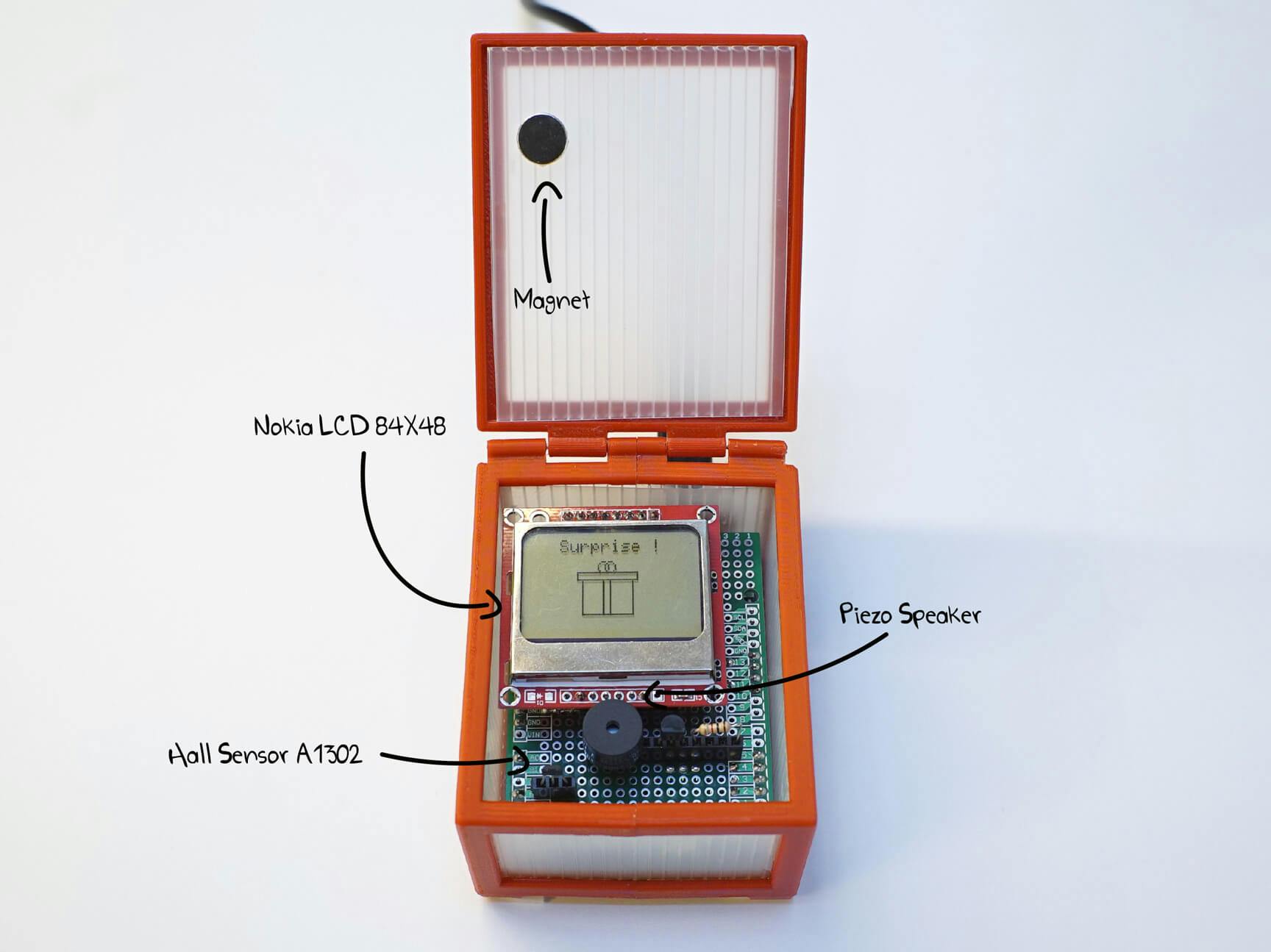
If you’d like to get to grips with Hall-Effect sensors and what they can do, then be sure to check out our hall-effect-powered gift box.
How to choose a distance sensor
Application
Our first consideration should be where the component will be used. There’s a considerable potential for overkill, here; you don’t need LIDAR to know when someone’s passed through a door.
Accuracy
LIDARs and IR LED sensors offer excellent precision at long and very close range, respectively.
Range/Distance
LED and hall sensors are good for short distances. If you want to measure across an entire room, an Ultrasonic or LIDAR sensor is probably appropriate.
Footprint
The average LIDAR is bigger than an Arduino, and thus makes a poor match for very compact projects, where LED and Hall Effect sensors thrive.
Power Consumption
Ultrasonic and Hall Effect sensors are the most power-efficient we’ve listed, here, while LIDAR sensors are the least.
MEMS
Okay, so temperature and distance are more or less self-explanatory. But what exactly is MEMS? Well, it’s an acronym that stands for Micro-ElectroMechanical System. It covers tiny, fabricated machines, some of which are smaller than a micron wide. These machines form the basis of the accelerometers, gyroscopes and magnetometers which allow your phone to understand how many steps you’ve taken in a given day, for example.

How are they built?
The production of MEMS devices takes advantage of the same fabrication methods widely used in integrated circuit manufacture. As such, they can be made efficiently and cheaply. There are two approaches to the ‘micromachining’ through which MEMS devices are made: bulk and surface. The former is a subtractive method which involves progressively removing layers of material from a surface using chemical or laser etching. The latter, meanwhile, is additive – with tiny layers of material being built in layers, much like in a stereo-lithographic 3D printer.
Accelerometers
Accelerometers measures acceleration forces. These forces could be static, like the constant force of gravity, or dynamic, like those caused by the movement of the device.
There’s more than one way to build an accelerometer, but each includes micro-mechanical structures which move under force and thereby cause a change in the device's electrical properties. Many come with a tiny piezoelectric crystal inside, which, when stressed by sudden movement, will produce a measurable voltage. Others come with miniature structures that collectively carry a capacitance, which changes as one of these structures moves relative to the other.
More important than what goes on inside the accelerometer is the output it produces. You’ll find considerable variety, here; some accelerometers communicate digitally, while others put out a variable analog voltage. The Arduino, and the Raspberry Pi, can read both, but a digital accelerometer will free up computational resources, as it won’t need regular polling via an analogRead() command.
Nowadays, most accelerometers measure forces along three axes, and can vary in sensitivity and maximum swings We used SparkFun’s triple-axis accelerometer breakout board when we built our ‘Arduino Pet’ project. The pet will generate R2D2-style beeps and bloops whenever it changes feels some movement. All you need to do is drag it around on the end of a lead.
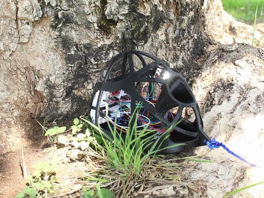
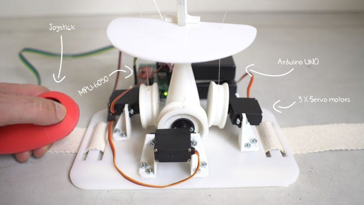
We also used an accelerometer in our animatronic tail project, specifically a combined triple-axis accelerometer and gyro, again from Sparkfun.
Speaking of gyros...
Gyro Sensors
A gyro sensor carries out a similar function to the accelerometer, except that it’s built to sense changes in angular velocity. You’ll find them on the wheels of cars, inside video-game controllers, and in the shake-correction hardware in a high-quality camera. They tend to work using a series of arms which bend towards and away from one another as the apparatus rotates.
Gyro sensors can measure angular velocity, and this information can be used to calculate the angles themselves over a longer period of time. They can also function as a vibration sensor, and be used to, say, measure (and correct for) the tiny movement of an attached motor. If you’re building robots, or need to measure precise inputs from the physical world, then you’re definitely going to be using a gyro sensor. Much like accelerometers, they come with a range of outputs and sensitivities, and so you’ll want to pick the one that best matches your project.
Magnetometer
A magnetometer measures magnetic fields in three axes relative to the earth’s magnetic field. They’re used in digital compasses for example. While there are some other technologies available, the overwhelming majority of modern magnetometers work via the hall-effect principle we’ve outlined.
Although you can find each of the MEMS sensors as a separate sensor, it’s common to find them in combinations of 2 or even 3. For example: the MPU6050 we used in our animatronic tail project incorporates both an accelerometer and a gyro.
How to choose the right MEMS sensor?
MEMS are unlike the other types of sensor we’ve mentioned here, since they’re defined by how they’re made rather than by the thing they measure. It’s not possible to compare accelerometers, gyros and magnetometers directly, as each serves a distinct purpose. What we can compare are different types of accelerometers, gyros and magnetometers: for example, DC versus AC accelerometers. This goes a little beyond the scope of this article – but we may just return to the topic in a future entry!
Color/Light Sensors
The spectrum of light is far broader than the visible portion. We measure light in frequency or wavelengths: we perceive different frequencies as different colours:
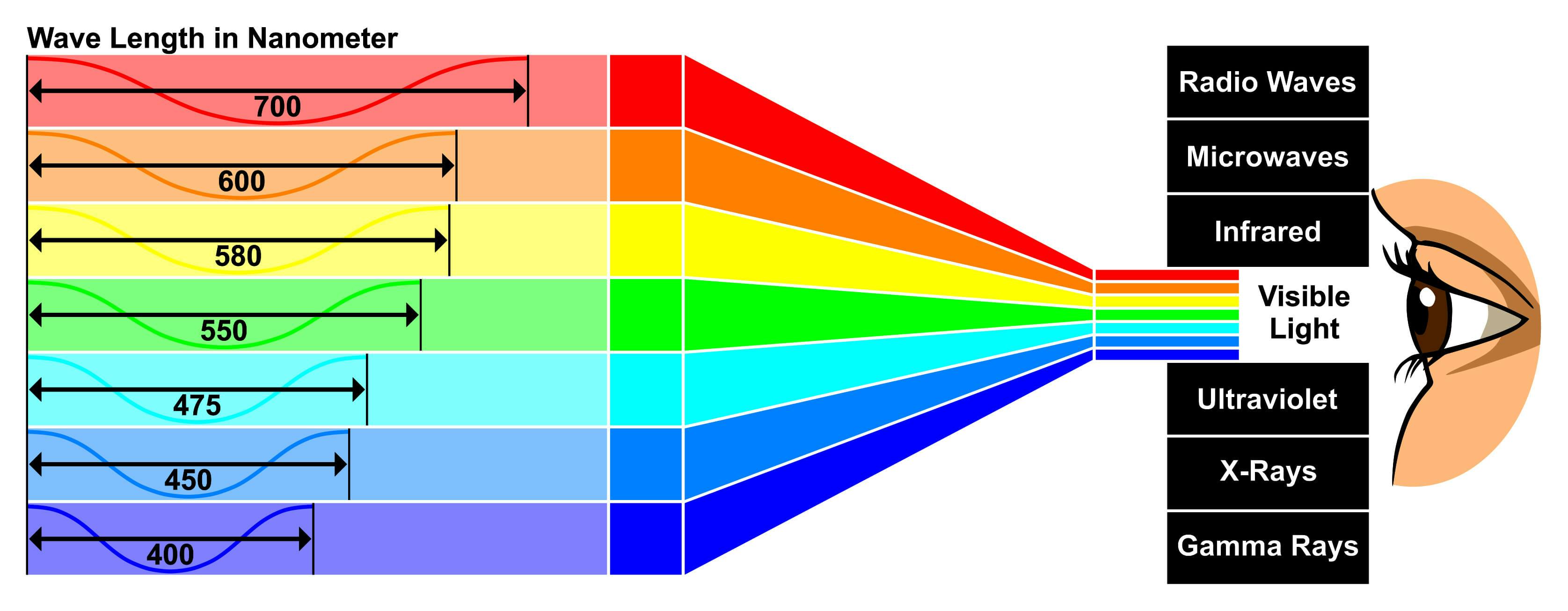
We can calculate the frequency of a given beam of light using the equation below. Frequencies higher or lower than the visible spectrum are known as infra-red or ultra-violet. As such, there's more to light-sensing equipment than just replicating the human eye in digital form. If you want to detect information being sent over an infra-red remote control, you'll need an infra-red sensor.

To measure the different parts of the spectrum, you’ll need to use different sensors that respond to the light frequency you want to measure.

LDR
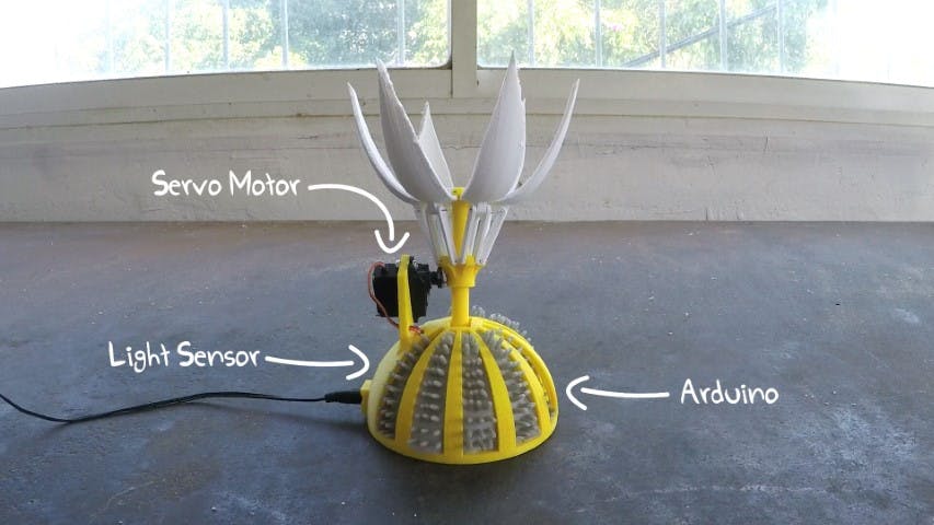
The simplest form of light-sensor is the Light Dependent Resistor, or LDR (or photo-resistor). The LDR's resistance drops when exposed to light, compared to the resistance value measured in the dark. In other words, the measurement sampled from the LDR is that of the resistance, rather than the light itself. We’ve used and LDR in our mechanical sunflower, whose 3D-printed petals unfold whenever the sun rises.
RGB Light Sensor
An RGB light sensor works by sending out pure white light and measuring the wavelength of the reflection. The response is sent through three separate filters so that the red, blue and green components are turned into a current, which in turn is transmitted to the Arduino via a digital serial communication.
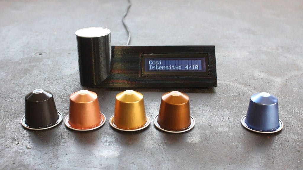
Light sensors form the basis of the CCD sensor found in digital cameras, but they’re also extremely useful in industrial sorting machines, where they’re used to filter manufacturing defects out of production lines at lightning pace. But they’re also great for domestic use. For example, we’ve put together an Arduino-based circuit for detecting the color of a coffee capsule and displaying the relevant information on an LCD screen. And once you’ve gotten it working, you’ll be able to apply the same circuitry to a range of other solutions.
How to choose a light sensor
Spectrum (IR, specific color, ambient light)
The complex information put out by an RGB sensor allows you to sense for a specific combination of colors. By contrast, a photo-resistor will simply vary according to the overall incoming light.
Temperature Sensitivity
Given that LDRs will vary in resistance as the temperature rises and falls, they’re a poor match for situations where the temperature is going to fluctuate.
Refresh rate
An LDR can respond to a small change in light in a few milliseconds, but if going from total light to total darkness, or vice versa, it can take a second or longer for the change to fully register. RGB sensors are comparatively zippy.
Touch/Force Sensors
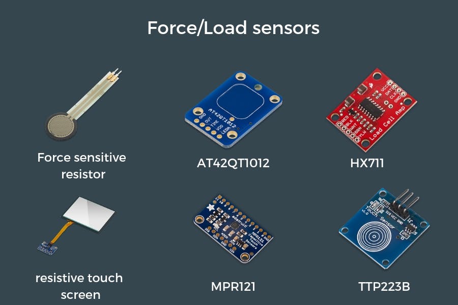
Force and touch sensors convert physical force into electrical signals. Like the other sensors we’ve mentioned, these come in several different varieties, each suited to a slightly different application. Force-sensitive sensors are found in a many devices such as mobile phones, digital scales and also in your car, as part of the airbag triggering system.
Touchscreens
The most obvious sort of force-sensitive sensor is the one most of us carry around in our pockets every day: the touchscreen on our mobile phones. Touchscreens come in two varieties: resistive and capacitive.
Resistive touchscreens are made from layers of conductive material, arranged to detect the presence and location of pressure at a given moment. They’re able to respond to even very small amounts of pressure, from just about any object, but they aren’t quite as fast to update as the capacitive touchscreen you have on your phone.
Capacitive touchscreens are built differently, and rely on the conductive properties of the human finger to work. A sheet of transparent conductor is placed behind a sheet of insulator, like glass. When a finger is pushed against the latter, it’ll cause a change in the electrostatic field of the former. This information can be used (through software) to quickly deduce where the finger is. Even if there are multiple simultaneous contacts on a capacitive touch device, the computer will be able to work out where they are.
FSRs
A force-sensing resistor is a kind of mechanical pressure sensor built from a conductive print, consisting of a zig-zag of narrow traces, placed slightly below a conductive film. As pressure is applied, the two move closer to one another, and the current is able to flow more easily through the entirety. You can even make your own FSRs using a piece of conductive sponge. Squash it, and the space within will shrink, allowing current to flow more easily.
FSRs are very cheap. You can usually pick one up for just a few dollars. However, they aren’t very precise – and so they make poor matches for electronic scales and other such pieces of equipment.
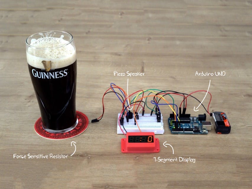
But for certain pressure-sensor applications, these extra features aren’t necessary. We used an FSR in our St. Patrick's day project, the ‘chug-meter’. It combines an FSR with a coaster to measure the weight of a pint of Guinness, starting a timer once the pint is off the coaster, and stopping it when the pint is put back.
Load Cell
Strain-gauge load cells work very differently than force-sensitive resistors, but they exploit the same basic principle. When a tightly-packed region of zig-zagging wiring is compressed, the resistance decreases. The ‘strain gauge’ itself is a zig-zag pattern printed onto a flexible substrate. When force is applied, it becomes more conductive. A typical strain-gauge load switch incorporates four of these devices, with an average being taken from each. Thus most load cells are accurate to within 0.1%, which compares very favorably with their FSR counterparts. There are other varieties of load cell available, including hydraulic and pneumatic ones, but thanks to their lower production costs, strain gauges represent a growing majority of load-cells available.
Load cells, of every sort, come with their downsides. They tend to be bulky and expensive, and they can be unreliable if overloaded, improperly mounted, or exposed to a corrosive environment. This is in marked contrast with FSRs, which are a little more robust.
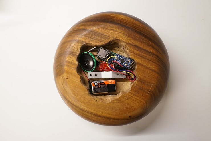
We’ve used this component in our April-fool ‘Evil fruit bowl’ which squeals in agony (or plays any sound you decide to load up) every time a piece of fruit is removed from it. It’s the accuracy of the load cell that allows for this to happen consistently – it’s precise enough to be able to detect the difference when a single banana is removed from a fully-loaded fruit bowl.
How to choose a touch/force sensor
Accuracy
Load cells are the most accurate type of force sensor. while FSRs are the least.
Max/min force
A load cell can also tolerate far greater differences in pressure than any other sort of force sensor. The more expensive ones can precisely weight up to a hundred kilos or more.
Interface
A resistive touchscreen, with its digital connectivity, offers the most straightforward interface of the sensors we've listed.
Footprint
The footprint on a force-sensitive resistor can be made very small indeed - and they're also completely flat. By contrast, a strain-gauge load cell is extremely bulky and thus unsuitable for most home-electronics applications.
Conclusion
Hopefully by now you've got an idea of the sorts of Arduino sensors available and what each of them do. There's plenty more detail to get into, and there's plenty of information out there on each of the sensors we've mentioned. If you want to try to get to grips with any of them, then why not start by putting together some of the sample projects we've linked to?

